Joining
Crimping
Techniques
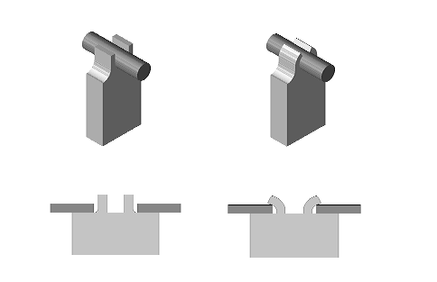
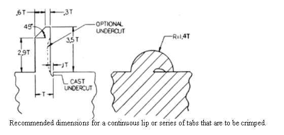
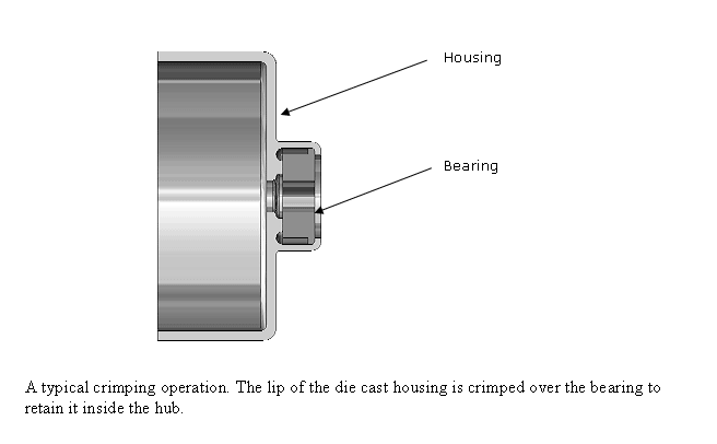
Crimping displaces metal by a combination of bending and compression. The casting must be designed to provide the required projection(s) or a continuous feature of the proper size and shape. There must be a surface to receive backup tooling, and all features of the casting affected by the crimping loads must have sufficient strength.
If a tab or series of tabs is utilized, crimping is usually accomplished by a single compressive stroke of a tool with a configuration that directs the flow of metal and forms the desired final configuration.
A rotating tool such as a knurling tool can be used to crimp a continuous feature, such as a circular lip. Knurling tends to generate heat by friction, increasing the ductility of the metal and improving the quality of the crimp.
Because a crimped joint is formed partly by bending which induces tensile elongation in the external surface of the bend, casting quality is more critical than for operations, such as staking, that only induce compressive loads. The material to be crimped must have no macro porosity and the external surface of the bend must be free of significant surface defects prior to the crimping operation.
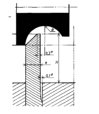
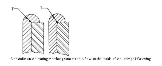
The amount of tensile deformation must be limited to the ductility of the metal, which is expressed quantitatively as percent elongation. However the force applied by the tool is directed in such a way that it induces compressive stresses in the entire cross section in addition to the bending loads. This reduces the net tensile stress in the outside surface and allows more severe deformation than would be permissible if pure bending were induced. Hence the bending radius can be reduced from the figure of around 6 to 9 times the material thickness that would be expected for a bending operation, to a minimum of 1.25 times the material thickness for a well-designed crimping operation.
Crimping Loads
Experimentation has shown that for crimping operations such as those shown below the load needed is dependent on the temperature of the material and is approximately:
At 20°C 800N/mm2
At 50°C 600N/mm2
At 80°C 500N/mm2
These figures apply to alloy ZP3, for the other alloys it will be somewhat higher. (ZP3 is the easiest alloy to form, requiring lower loads and achieving greater deformation without cracking. There are however plenty of examples of successful forming operations with ZP5 and ZP8)
