Finishing
Polishing and Plating
All of the zinc diecasting alloys featured in this publication can be readily polished and plated. Polished diecastings become highly reflective bluish white. Over time, the unprotected polished surface tarnishes to a dull grey colour. It is standard practice therefore to protect the polished surface with a clear organic coating or more commonly electroplate. Common decorative electroplate finishes on zinc diecastings are chromium, nickel, brass, silver, and gold. Of these only chromium and gold are really immune to tarnishing.
Not infrequently zinc alloy diecastings are given a thin electroplated coating of zinc, which is subsequently clear passivated. Any finishing prior to this is usually limited to vibratory treatment. The reason for applying the zinc is to achieve a bright passivated finish, only alloy ZP3 can be consistently clear passivated successfully. However clear passivation whether on ZP3 or pure zinc is only suitable for indoor use and its wear resistance is very limited.
Barrel Plating
Small zinc diecastings are frequently barrel plated with copper followed by nickel. (It is not possible to apply chromium by the barrel process). Barrel plating is much less costly than rack plating because no individual handling of components is required, but it is not used for larger castings because of the impact damage that results from the tumbling action. The difference in the costs of barrel plating simple and complex shapes is relatively small, provided that the barrel plating is feasible and drag-out losses and plating time are minimized. Small rounded protrusions or raised edges are useful on flat surfaces to prevent lodging and sticking during barrel plating.
Castings are sometimes electroplated or electroless plated for reasons other than appearance, for example for increased wear resistance, ease of soldering, improved electrical properties. The component design for electroless plating is not so critical as for electroplating, as the coating builds up evenly on all surfaces whatever their shape.
Design of Castings to be Plated
The desire to produce a high quality electroplated finish on a diecasting has major implications to its basic design. The surface of a zinc alloy diecasting to be electroplated must be substantially free of surface defects. This in itself has some implications to the design of the component as the positioning of the gate becomes more critical and its cross sectional area may need to be larger than for those components requiring functional or other finishes. A great deal of thought also needs to be given to how the part will be polished and parting line witnesses removed or disguised. It will often be found that these considerations have major effects on the component design arrived at. Another factor that must be considered is the tendency for electroplate to build up on convex surfaces and external corners of the component and conversely to thin down on concave surfaces and internal corners. Highly reflective finishes should never be applied to critical surfaces that are totally flat as the slightest deviations from that flatness due to manufacturing and finishing variations will be highlighted.
Design procedures to accommodate the plating process have been established to minimize finishing and plating costs, promote an even distribution of plating metals, and ensure adhesion. Departures from these procedures may impose cost penalties and reduce performance. The remainder of this section is based upon extensive experience in chrome plating zinc-alloy diecastings. The specifics will therefore be confined to that area. General principles drawn from these specifics may be applied more broadly to the other zinc alloys and processes.
During “chromium plating” zinc diecastings are sequentially electroplated with copper, one or two layers of nickel, and chromium. The thickness of each layer is rigidly controlled according to the user’s own specifications. Finishing operations such as buffing, polishing, or vibratory finishing, together with plating costs, can account for over a half of the total product cost.
The casting must be designed to minimize finishing problems by positioning the parting line, gates, vents, overflows and ejectors to avoid or minimize marks left after breaking or shearing. Where possible, they should be located on non-significant surfaces. The gates, vents and overflows must also be located and be of such size to produce sound castings with good surface quality. Close interaction with the diecasting and plating sources from the earliest stages of design is essential in meeting these varying, and often conflicting criteria.
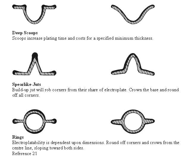
Casting details may significantly affect plating costs because electric current is not distributed equally throughout a plating tank. It is concentrated along the paths of least electrical resistance. The complexity and shape of the casting influences the current density, and hence the buildup of plating material. Good uniformity of plating thickness is obtained only on gently curving, convex surfaces. Corners, edges, fins, ribs and other projections “steal” more than an equal share of electrodeposited metal. Conversely, grooves, serrations, holes, concavities and deep recesses are “starved” of their share.
The area that receives the thinnest electroplate is commonly the area of first failure. Specifications recognize this fact by requiring a minimum thickness of electroplate on any area exposed to view during service. Plating techniques such as the use of shields, cathode robbers, and auxiliary anodes can help to equalize the plating thickness, but proper casting design is usually the most effective means of cost control.
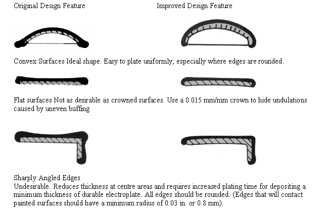
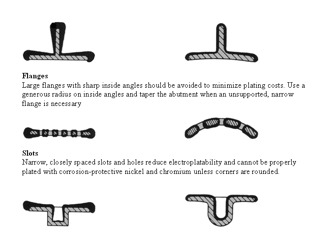
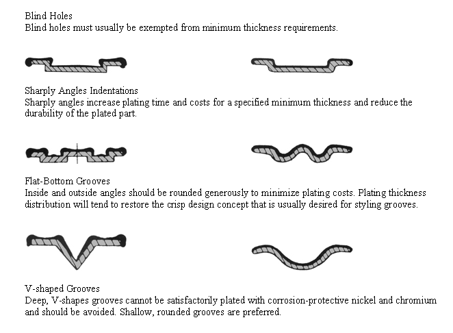
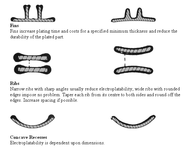
Design provisions for polishing, buffing and electroplating operations are normally a compromise between what is functional, what is preferred by the plating source, and design styling requirements. The following list summarizes the principles illustrated by the diagrams beneath:
– Convex surfaces are preferred to flat surfaces. A minimum crown of .015 mm/mm is recommended to improve metal distribution and hide substrate imperfections that may arise from uneven buffing. If flat surfaces are considered essential to the design, a satin chromium finish rather than a bright chromium finish may hide, or at least not magnify surface waviness.
– All edges should be chamfered or rounded off to a radius of at least 0.4 mm, but preferably 0.8 mm. Small radii will be reduced appreciably by the electrodeposited metal, and tend to restore crisp lines. Sharp edges should be avoided for several reasons. First, they will become beaded during electroplating, which may destroy the design concept. Second, sharp edges in contact with painted surfaces may rupture the paint film and lead to rusting. Third, sharp edges complicate casting and electroplating operations, and they increase polishing and buffing costs because the sharp edges dislodge compound from the rotating wheels.
– The depth of concave recesses should be reduced as much as possible. Deep scoops with a depth greater than 50 percent of the width should be avoided. Otherwise, the plating time for a minimum thickness of electroplate is prolonged. Even when sidewalls are sloped and the inside and outside angles are rounded, plating time will be increased. The uniformity of electroplate thickness in apertures and deep recesses with a minimum diameter of 50 mm can be improved considerably by employing current shields to mask high current density areas, or special auxiliary anodes to focus supplemental current at the bottom and sidewalls of the recesses. These devices can minimize or eliminate the extra plating time that would otherwise be required. Shields and special anodes impose costs, but generally less than that imposed by an increase in the plating time. Typical plating cost premiums for parts with deep grooves and recesses, as a function of the ratio of depth to width (D/W), are summarized below. The percentages are an approximate cost premium for grooves with right angles rounded off to a radius of at least 0.8 mm. Higher costs can be expected if a high-quality mirror finish is required in the grooves or recesses, because costs of buffing, prior to plating, will be greater.
Plating cost premiums for parts with deep grooves and deep recesses (a)
| Depth/Width Ratio | Increase in Plating Time % | Approximate Premium in Plating Cost % |
| 1/2 | 20 | 12 |
| 5/8 | 40 | 24 |
| 3/4 | 60 | 36 |
| 7/8 | 80 | 48 |
| 1 | 100 | 60 |
(a) Approximate cost premium for grooves with right angles rounded off to a radius of at least 0.8mm. Higher costs can be expected if a high quality mirror finish is required in the grooves or recesses because costs of buffing, prior to plating will be greater.
– Flat-bottom indentations should be rounded off and their depth limited to 50 percent of their width. Deep indentations generally increase plating costs, depending on the width and the radius of the angles between perpendicular planes. Suggested radii for specific indentations are summarized below. The inside and outside angles of indentations, may, of course, be chamfered or bevelled instead of rounded. In such cases, the minimum angle defined by the chamfer should be 100°.
Minimum Radii for Angles Defined by Indentations
| Depth of Indentation
mm |
Minimum Radius of Angle Between Perpendicular Planes, mm |
| 1.60 | 0.4 |
| 3.20 | 0.8 |
| 6.40 | 1.6 |
| 9.50 | 2.4 |
| 12.7 | 3.2 |
If sharper angles are required for functional purposes, minimum thickness requirements may not be met at inside right angles, and corrosion resistance will be deficient at the offset peripheries of the indentations. ASTM designation 142- 58 includes the statement that holes, recesses, and the bases of angles are normally exempt from requirements for significant surfaces and suggests that significant surfaces be defined as those parts of the visible surface that can be touched with a 19.0 mm diameter sphere or a diameter agreed upon by the manufacturer and the purchaser. Many purchasers no longer use this procedure for defining exemptions.
– When sharply angled grooves are desired for specific decorative effects, an organic finish is recommended for protecting the bottom of grooves. Such a finish, applied after plating, contrasts sharply with the mirror-like areas of the plated surfaces between grooves. The painted finish usually costs less than the premium for plating the bottom of the grooves if a minimum specified thickness of copper plus nickel is required.
– Slots and holes should be widened to at least two times their depth, and slots should be spaced to make the distances between centres at least four times their width. The complications imposed by slots and holes can be minimized by chamfering or bevelling the edges. Circular or elliptical contours between slots are preferred to square or rectangular shapes.
– The number of blind holes should be minimized, and their depth limited to one half of their width. Diameters less than 5.6 mm should be avoided; otherwise the electroplate thickness within the holes will be inadequate. Blind holes on opposite sides of a part must be avoided or drag-out losses (entrapment of plating solution in the casting) will be excessive.
– Threaded holes should be countersunk to minimize electroplate buildup at their peripheries, expediting the insertion of fasteners after plating. The electroplate distribution in threaded, ribbed or fluted holes will be uneven, and this must be taken in to consideration for surfaces which mate in subsequent assembly. Threaded, ribbed, or fluted holes may also entrap cleaning materials or plating solutions, which can cause corrosion, particularly where steel fasteners are in contact with zinc castings. Some manufacturers prefer to tap threads after plating to ensure that no plating fluids remain.
– The height of fins or ribs, if required, should be reduced as much as possible. A generous radius greater than 1.6 mm is suggested at each base. Pointed tips should have at least the same radii. Parallel finds should be spaced to make the distance between centres at least four times the fin width so that the lands between the fins will receive an adequate thickness of electroplate. In general, broad hollow ribs or fins are preferred to slender, solid ones.
– Flanges perpendicular to, and shielding face areas, reduce metal thickness uniformity and prolong the plating time. Short flanges of 6.4 mm or less may be acceptable if the inside angles are rounded with a radius of 2.4 mm or more. Sides should be sloped with a 3° taper, and protruding edges should be rounded generously.
– Recessed letters are recommended rather than raised letters for insignia. Edges should be rounded with gentle contours. A decorative paint in shallow recessed symbols provides excellent contrast with chrome electroplate. If raised letters are necessary, those with a height of 50 percent or less of the width are easier to plate than higher letters. Some designers specify a maximum height of 4.8 mm. Corners and edges should be rounded; otherwise surfaces adjacent to small apertures will be deficient in electroplate thickness. Tapered sides to the lettering are recommended.
– Peripheral contours with a circular or elliptical form promote uniform electroplate thickness. Spars, fingers and other peripheral projections reduce uniformity and prolong the plating time. Irregular peripheral projections with flat perpendicular sides “steal” an excessive amount of current during plating.
– Integral studs for fasteners should have as low a profile as possible, and inside angles at each base should be rounded generously. Tips must be similarly rounded. Otherwise the inevitable thick deposit at the tips will increase dimensions beyond acceptability. If studs are threaded before plating, thickness is limited on significant surfaces to only 0.005 to 0.0075 mm. In general, an allowance of five times the average electroplate thickness should be made. Special threads must be adopted if thicker coatings are required.
– Studs or bosses with hollow centres should be shortened as much as possible and angled 90° from the major plane of the casting. All bosses should face the same direction to facilitate racking and electroplating.
– Drain holes must be provided in cup-like contours to avoid the costly supplementary hand rinsing that otherwise would be required between cleaning and plating operations. Tubular articles should also have provision for complete drainage to prevent drag-out. Alternatively, tubes should be completely sealed.
Complex shapes may trap air bubbles during the plating process, causing areas to be improperly plated. Also, suspension points are required which give good electrical contact between the part and the rack during electroplating. Such a point may be a hole, thread, or a lug, preferably located where surface appearance is unimportant.
Effects of Casting Features on Electroplating
Platability Factors
Features are exaggerated for purposes of illustration
