Design
Design Rules
General rules must never be considered as hard and fast in their application. Used with judgment, however, they will lead to a design that is logical, efficient and helpful in attaining low cost. There are often sound reasons for exceptions. A check of a design against the points listed below will help to reveal oversights and indicate possible desirable changes
Parting Line Geometry
Die casting dies must be made in at least two parts, which join at the parting line and which will therefore leave a ‘witness’ on the die casting even after trimming.
The parting line of the die is dictated largely by the design of the component. It must usually be at the maximum diameter or section of the casting. Die costs and flash removal costs are minimised when the parting is in one plane at right angles to die motion. It is also easier to maintain a flat parting line flash free.
The designer should establish the position of the parting line so as to minimise the effects of the ‘witness’. It is often more aesthetically pleasing to create a bead at the parting line and this can simplify any required flash removal).
Exacting tolerances are very difficult if not impossible to achieve on parting line dimensions.
Complex parting lines are possible and are frequently used because they offer greater component design freedom.
The position and length available for the liquid metal to flow in to the cavity should be born in mind when arranging the parting line. If the only available position does not give the opportunity for metal to flow directly into all parts of the casting then good surface finish and low porosity will be more difficult to achieve.
It should also be remembered that adequate gate area will be needed and if the gate length is restricted the gate will need to be thick with possible consequent trimming problems and a heavy witness mark. Such problems can often be overcome at the initial design stage by changing the geometry of the component.
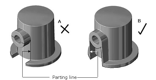
For castings to be made in two part dies avoid vertical parting lines (ie those lying in the direction of die movement on opening) this will give stronger die construction, less flash formation and simpler trimming.
Parting lines for parts requiring extra moving parts are dictated largely by the requirement to achieve good “shut outs” between the various die members, which are easy to maintain during production. Again parting lines which lie on a flat plane are easier to produce and maintain. Avoiding vulnerable die features should again be born in mind when considering the parting line of such dies.
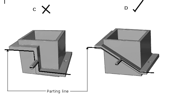
Examples of bad and good design for parting line geometry
| AA broken parting plane can leave traces of flash on the castings which are difficult to remove | BA simple modification greatly facilitates trimming, and improves the strength of the component. |
Avoid split lines running parallel to the direction of die opening wherever possible, this will give stronger die construction, less flash formation and simpler trimming.
Example (D) achieved this in a part with all the same design elements as in (C).
Section Thickness
Wall Thickness
Thin wall sections are proportionately stronger than thick ones. Designs incorporating fairly even thin wall sections use less material and can be produced more quickly. This helps to keep costs down.
The minimum practical wall section depends on its distance from the ingate (the position where molten metal enters the die cavity proper). As a rule of thumb, for short distances, say less than 50mm, it is less than 0.5mm, ranging up to 2mm at about 200mm. (Application of computer aided runner and gating techniques give a better indication of minimum achievable wall sections where this aspect is critical.)
There is no critical upper limit to wall thickness but very few parts are made with wall sections above 6mm.
Section Ratios
Ideally the section thickness of a zinc alloy diecasting should be fairly constant throughout. In practice however reasonably wide section ratios are practicable. As an aid to achieving the required uniformity the following technique may be found useful:
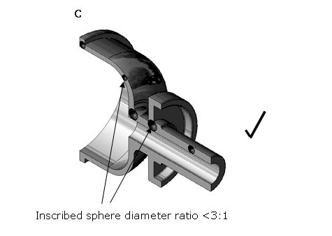
Check the design for changes in section thickness by comparing the sizes of imaginary spheres that can be fitted into the sections. Do not neglect the third dimension. If the diameters of the spheres differ by more than 3:1, shrinkage porosity may occur in the thicker areas. If the diameters of the spheres differ by more than 6:1 the effect will be severe and strength will be significantly reduced in that area.
Checking Thickness Ratios Using The Inscribed Sphere Technique
In example A, sphere diameter ratios are 4:1 which would predict the occurrence of porosity as illustrated in B

When the component is redesigned to reduce the ratio of inscribed sphere diameters, as in C below, porosity is avoided and material is saved.
Draft Angles
Normal minimum requirement 1° internal, 0.5° external
Round holes 0.1°
Shallow ribs require more taper (5-10°), although for ribs that are in line with shrinkage, as for instance the spokes of a wheel, small tapers are more acceptable.
For critical features 0° can be reliably achieved in some cases (consult a diecaster who is familiar with achieving this goal). Some increased cost will inevitably be incurred but this will usually be outweighed by the cost of the machining operation otherwise needed. All features with such negligible draft angles must be formed from the moving die half or by moving die members (The casting must move back with the moving die half when the die opens) and provision for positive square ejection must be made to prevent the casting sticking on the moving die.
Maximum Depths of Cored Holes
| Hole Diameter mm | Blind Hole Max. Depth mm |
Through Hole Max. Depth mm |
| 3 | 9 | 24 |
| 4 | 20 | 37 |
| 5 | 30 | 47 |
| 6 | 45 | 57 |
| 7 | 60 | 70 |
| 8 | 75 | 80 |
| 9 | 90 | 90 |
| 10 | 100 | 100 |
| 11-20 | 10x diameter | 10x diameter |
| >20 | 12x diameter | 12x diameter |
Design to Assist Die Filling
When considering the parting line of the component, the position and length available for the ingate should be born in mind. If the available position does not give the opportunity for metal to flow directly into all parts of the casting then good surface finish and low porosity will be more difficult to achieve. It should also be remembered that adequate gate area will be needed and if the gate length is restricted the gate will need to be thick with possible consequent trimming problems and a heavy witness mark.
Component design should be such that the metal fills the die smoothly and without turbulence to avoid surface imperfections. Generally the more uniform the wall thickness the easier this is to achieve.
Obtaining a fast smooth die fill
Ribs
Ribs are an excellent way of strengthening a casting without thickening. They should be rounded and blended and wherever possible arranged to join adjacent sections to provide mutual strengthening and assist die filling.
Thin flat plates can be strengthened and die filling assisted by adding ribs. Shallow, rounded, well-distributed ribs are best, since they are less likely to cause distortion of the casting after ejection from the die.
Avoid thick sections at intersections of ribs or shrinkage porosity may occur at these points.
Flat Surfaces
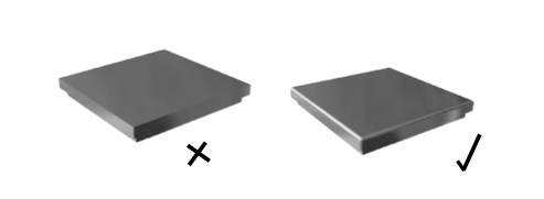
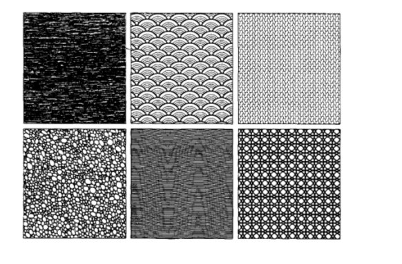
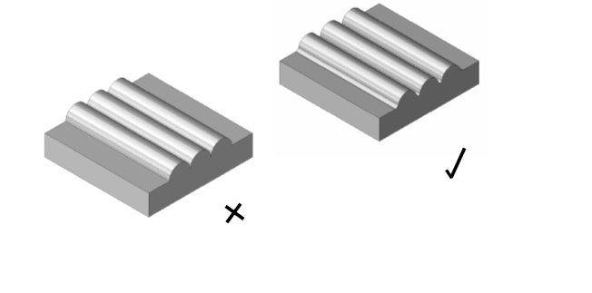
Flat smooth surfaces are probably the most expensive and least attractive design feature on a diecasting. There are several ways of producing a more attractive appearance and reducing the cost of production. Avoid completely flat decorative surfaces; they highlight any tiny imperfections. If the surface is to be polished it should be “crowned”. If a flat surface is necessary surface quality is actually improved by texturing or a pattern of small ribs, and these features also tend to mask surface imperfections.
Crowning
Where a plain flat highly finished surface has to be specified, slight crowning and rounding of the corners will reduce distortion, aid metal flow and improve the appearance.
Textured Surfaces
Some of the many hundreds of surface effects that can be produced by using textured dies. As well as enhancing the appearance of the components, the surface quality is actually improved.
Fillets and Blends
Sharp corners are always a source of weakness and should be avoided by the use of fillets. Even the smallest fillets have an appreciable strengthening effect. A radius of 0.4mm minimum is suggested in place of sharp corners and larger radii are desirable when conditions permit their use. Fillets of 0.4mm radius are barely noticeable even on outside edges and, in fact, 0.8mm radius is seldom evident except on close inspection.
It is common die casting practice to use a fillet having a minimum radius of 1.6mm on inside edges. A slight radius on outside corners of castings reduces die cost and promotes the durability of any subsequent finish. Buffing or polishing is apt to cut through the finish at sharp outside edges, while organic finishes tend to thin out and give inadequate protection along sharp edges.
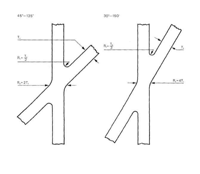
Design of Transitions and Fillets
Diagrammatic section showing junctions of walls of unequal thickness
Diagrammatic plan showing examples of angled intersections
Lettering
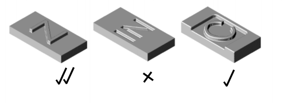
When die cast lettering, numerals, trademarks, diagrams or instructions are required they should be designed and placed to facilitate die construction and removal of the casting from the die. Lettering in the die can be produced by engraving (high speed milling) or by spark erosion.
Normally, the designer should specify raised lettering because it is easier to cut a design into a die surface than to make a raised design on the surface. Depressed lettering on the casting is much more expensive in die cost, and deteriorates with time because of erosion by the molten alloy. If sunken lettering is essential it is best produced by spark erosion when the die cavity proper is produced. When engraved letters may not project above the surrounding surface of the casting, raised engraving on a panel sunk into the surface of the casting can generally be used.
Engraving is preferably done on surfaces parallel or nearly parallel to the die parting. It must never constitute an undercut, which could interfere with ejection of the casting from the die. Minimum width of the upstand is 0.25mm and the flank angle should be 25° or greater, and the height should be equal to or less than the upstand width
Inserts
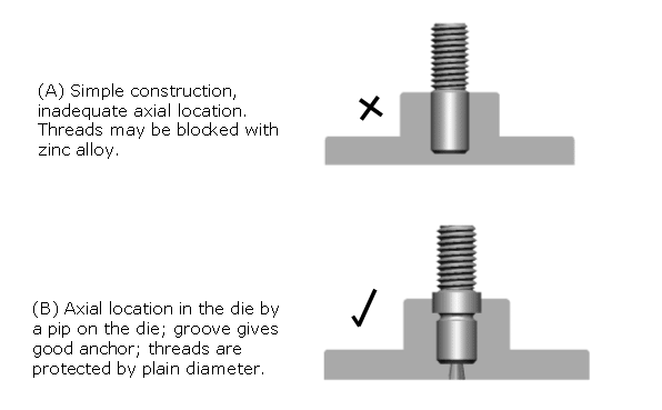
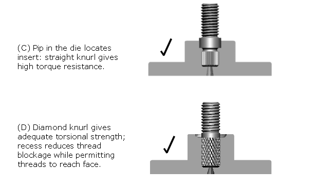
Cast in inserts are much less frequently used now than in the past, because placing them in the die slows the process and hence increases costs. It generally costs less to press in inserts after casting. However when this is not possible cast in inserts can still be used.
Features to be considered when inserts are to be used
Dimensional Tolerances
The capability of producing complex components with excellent precision at low cost is one of the main advantages of the zinc alloy diecasting process. However it is important not to specify smaller tolerances than are necessary because they incur extra die maintenance and quality control costs. Four groups of tolerance bands appear below varying from the best achievable to those that involve minimum casting cost. Which to apply to the individual dimensions of a casting design depends on the function of part and the cost saved by the avoidance of any machining. It is vital to confer with a diecaster conversant with producing precision castings when specifying tolerances in the “best achievable” range.
Best Achievable Linear Tolerances
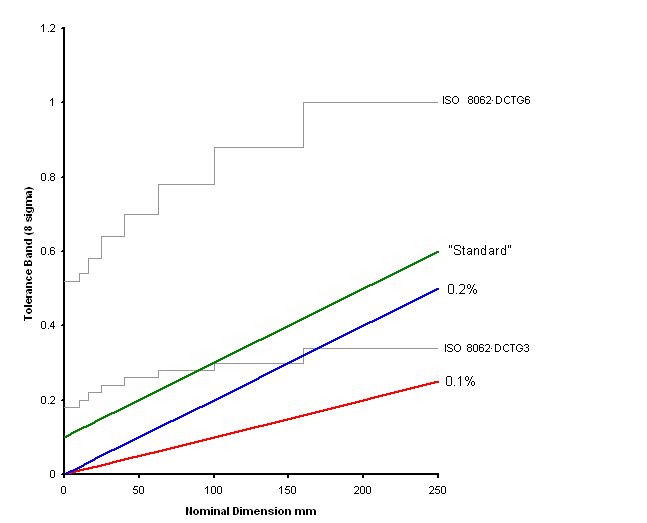
Currently best diecasting practice allows a linear tolerance band within 0.1% of dimension at the 8 standard deviations confidence level. This degree of precision can only be targeted when the geometry of the component is favourable to consistent shrinkage without distortion following ejection from the die. It is vital to work closely with a diecaster when specifying precision at this level, and it can be expected that some adjustment to die dimensions will be required following initial casting trials. Also statistical process/quality control techniques will need to be employed to ensure conformance.
It is much easier to achieve such small tolerances on features formed by one die member, although studies prove that it sometimes possible on cross parting line dimensions. However such tight cross parting line tolerances demand more frequent maintenance because the dimensions are affected by wear between the mating surfaces of the die.
Normal Minimum Linear Tolerances
A “normal” minimum linear tolerance band is 0.2% of dimension at the 8 standard deviations confidence level. Again it may be necessary to adjust die dimensions following initial die trials, but SQC/SPC may not be necessary. Note that for dimensions below about 150mm this tolerance is increasingly superior to the minimum tolerance indicated by ISO8062 DCG3 as being the tightest for zinc alloy diecastings. Again these tolerances are much easier to maintain for dimensions formed by one die member.
“Standard” Tolerances
The term “standard” here means the closest tolerance that can be expected at first die trial. Hence avoiding the cost of adjusting the dimensions of a hardened steel die and the time delays involved. It is arrived at by adding 0.1mm to the “normal minimum tolerance”. Hence the tolerance band is 0.2% of the nominal dimension plus 0.1mm.
ISO8062 Tolerances
ISO standard 8062 covers dimensional tolerances for cast metals, it is currently undergoing revision. The linear tolerances indicated for zinc alloy diecastings in ISO8062 are between grades DCTG3 and DCTG6. The tolerances indicated by these specifications are shown on the graph below overlaid by the “best”, ”normal minimum” and standard tolerances indicated above. It is clear that at least for the smaller dimensions the ISO standard seriously underestimates the precision capability of the process.
The ISO standard also covers geometric tolerancing, at present no surveys are available to show how the repeatability of production castings compares to these geometric tolerances. It is expected that, at least for the smaller dimensions, the precision capability will be much superior to that indicated by ISO 8062.
Economic Tolerances
It is generally unnecessary to specify very fine tolerances for all dimensions in any one casting. Usually they need to be held only on a few critical dimensions. The following standards have been compiled as a guide to tolerances for production at the most economical level and they cover values consistent with fast uninterrupted output, maximum die and tool life, and low maintenance costs. Similar considerations apply to all mass production processes. Conformity with these standards will ensure dependable service at the most economical casting cost. It is suggested that these standards are applied to all non-critical dimensions of the casting design.
These tolerances can be expected to be achieved first time, ie without adjustment of die dimensions, which will minimise production lead times.
Economic Linear tolerances
1. Tolerances In One Die Half
| Dimension mm |
Tolerance mm |
| 0 – 25 | 0.10 |
| 26 – 32 | 0.12 |
| 33 – 40 | 0.14 |
| 41 – 50 | 0.16 |
| 51 – 63 | 0.18 |
| 64 – 80 | 0.20 |
| 81 – 100 | 0.24 |
| 101 – 120 | 0.28 |
| 121 – 160 | 0.36 |
| 161 – 200 | 0.44 |
| 200 – 250 | 0.54 |
| 251 – 320 | 0.68 |
| 321 – 400 | 0.84 |
| 401 – 500 | 1.04 |
| 501 – 630 | 1.30 |
| 631 – 800 | 1.64 |
| 801 – 1000 | 2.04 |
| 1001 – 1200 | 2.44 |
| 1201 – 1600 | 3.24 |
| 1601 – 2000 | 4.04 |
2. Tolerances Across Die Parting (Related To The Longest Diagonal) And Based On A Single Cavity Die
|
Dimension mm |
Longest Diagonal mm | ||||
| 0-180 | 180-260 | 260-370 | 370-525 | 525-750 | |
| Tolerance mm |
Tolerance mm |
Tolerance mm |
Tolerance mm |
Tolerance mm |
|
| 0 – 25 | 0.26 | 0.30 | 0.40 | 0.50 | 0.70 |
| 26 – 32 | 0.28 | 0.32 | 0.42 | 0.52 | 0.72 |
| 33 – 40 | 0.30 | 0.34 | 0.44 | 0.54 | 0.74 |
| 41 – 50 | 0.32 | 0.36 | 0.46 | 0.56 | 0.76 |
| 51 – 63 | 0.34 | 0.38 | 0.48 | 0.58 | 0.78 |
| 64 – 80 | 0.36 | 0.40 | 0.50 | 0.60 | 0.80 |
| 81 – 100 | 0.40 | 0.44 | 0.54 | 0.64 | 0.84 |
| 101 – 120 | 0.44 | 0.48 | 0.58 | 0.68 | 0.88 |
| 121 – 160 | 0.52 | 0.56 | 0.66 | 0.76 | 0.96 |
| 161 – 200 | 0.60 | 0.64 | 0.74 | 0.84 | 1.04 |
| 200 – 250 | 0.70 | 0.74 | 0.84 | 0.94 | 1.14 |
| 251 – 320 | 0.84 | 0.88 | 0.98 | 1.08 | 1.28 |
| 321 – 400 | 1.00 | 1.04 | 1.14 | 1.24 | 1.44 |
| 401 – 500 | 1.20 | 1.24 | 1.34 | 1.44 | 1.64 |
| 501 – 630 | 1.46 | 1.50 | 1.60 | 1.70 | 1.90 |
| 631 – 800 | 1.80 | 1.84 | 1.94 | 2.04 | 2.24 |
| 801 – 1000 | 2.20 | 2.24 | 2.34 | 2.44 | 2.64 |
| 1001 – 1200 | 2.60 | 2.64 | 2.74 | 2.84 | 3.04 |
| 1201 – 1600 | 3.40 | 3.44 | 3.54 | 3.64 | 3.84 |
| 1601 – 2000 | 4.20 | 4.24 | 4.34 | 4.44 | 4.64 |
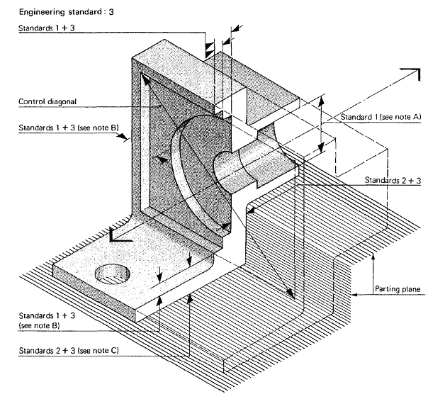
3. Additional Tolerances For Moving Die Elements
When moving die elements are needed to enable the casting to be removed from the die, the tolerances in standard 3 should be addedto the tolerances in standards l and 2
| Longest Moving Die Half Diagonal, mm | Total Tolerance mm |
| 0 – 130 | 0.2 |
| 130 – 180 | 0.3 |
| 180 – 250 | 0.4 |
| 250 – 400 | 0.6 |
Note A: The dimension is influenced by the moving die element only and the tolerance is in accordance with standard 1.
Note B: The dimension is influenced by the moving die part and the die half in which it is mounted. The tolerance on dimension B is the sum of the value from standard 1 plus the value from standard 3 for the moving die part diagonal.
Note C: The dimension is influenced by the moving die element and the opposite die half. The tolerance on dimension C is the sum of the value from standard 2 for the parting longest diagonal plus the value from standard 3 for the moving die part diagonal.
Economic Geometrical Tolerances
In some circumstances customary dimensioning and tolerancing, however well applied, does not ensure that the components will assemble or function correctly. This section provides a means of tolerancing the geometrical characteristics of straightness, flatness, parallelism, squareness, angularity, concentricity, symmetry and position.
Geometrical tolerancing need not be applied unless the circumstances indicate that material advantages will accrue from the increased design work entailed. Drawings prepared for quantity production in workshops of widely varying equipment and experience are cases where this technique enables the design requirements to be expressed more exactly with advantage to the design, manufacturing and inspection departments.
Definition: A geometrical tolerance is the maximum possible overall variation of form or position about that shown on the drawing. In other words, it is the width or diameter of a tolerance zone within which the surface, or middle plane or axis of the feature is to lie It represents the ‘full ‘indicator movement in cases where testing with an indicator is applicable.
Geometrical tolerances are covered in ISO 1101:2004 Geometrical Product Specifications (GPS) — Geometrical tolerancing — Tolerances of form, orientation, location and run-out.
4. Misalignment tolerances
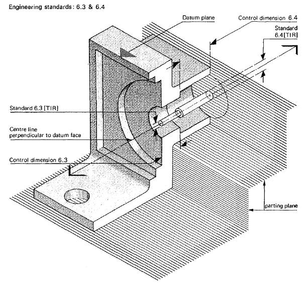
Concentricity of cylindrical surfaces or alignment of other shapes (male or female) is affected by the design of the diecasting. This standard applies to die castings that are reasonably rigid and uniform in shape and wall thickness. Under these conditions diecastings may be slightly out of true, but this deviation is allowed for as stated in standard 1, linear dimension tolerances. In some cases the effect of other applicable standards must be considered in determining misalignment tolerances, eg die parting tolerances, standard 2, additional moving die element tolerances, standard 3; and alignment tolerances for plane surfaces, standard 5.
Diecastings containing inserts are not covered by this standard.
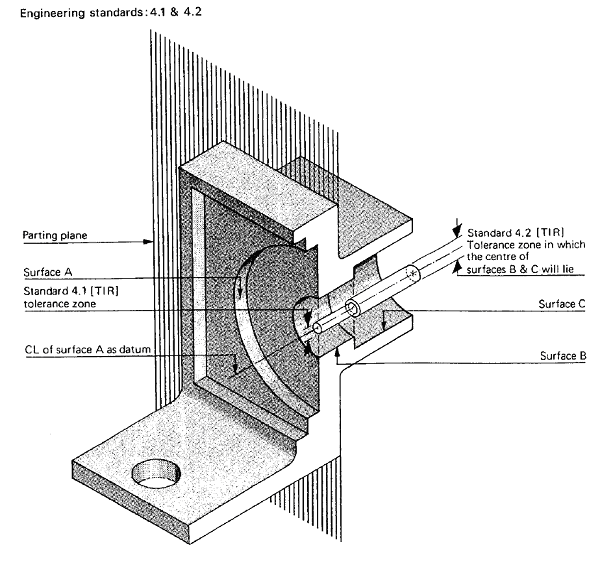
4.1.Cylindrical or other surfaces formed by the same die half
Cylindrical surfaces A and B formed by the same die half will be aligned to within 0.1 mm (TIR) irrespective of size. Under these conditions die castings may be slightly out of true but this deviation is allowed for as stated in standard 1.
4.2. Cylindrical or other surfaces A and C formed by opposite die sections
Note: The larger dimension controls the tolerance.
Total tolerance (TIR)
| Diameter A mm | Tolerance mm |
| 0 – 80 | 0.30 |
| 81 – 100 | 0.33 |
| 101 – 125 | 0.37 |
| 125 – 160 | 0.42 |
| 161 – 200 | 0.48 |
| 201 – 250 | 0.55 |
| 251 – 315 | 0.65 |
| 316 – 400 | 0.78 |
| 401 – 500 | 0.93 |
4.3. Alignment of holes formed by two moving die elements in the same die half
Note: The tolerance is based on the sum of the two dimensions A and B formed by moving die elements.
| Diameter A mm | Tolerance mm |
| 0 – 80 | 0.38 |
| 81 – 100 | 0.44 |
| 101 – 125 | 0.51 |
| 125 – 160 | 0.62 |
| 161 – 200 | 0.74 |
| 201 – 250 | 0.89 |
| 251 – 315 | 1.08 |
| 316 – 400 | 1.34 |
| 401 – 500 | 1.64 |
5. Alignment of plane surfaces: flatness, parallelism and squareness
Alignment refers to the angular departure from the designed relationship between the elements of a diecasting. The angular accuracy of a die casting is affected by numerous factors including the size of the die casting, the strength and rigidity of the die casting die and die elements under conditions of high temperature and pressure, positioning of moving die members, and distortion due to cooling strains and as a result of handling.
A casting with low section modulus cannot be kept flat during cooling as it has insufficient stiffness to resist various internal stresses that arise during cooling.
A casting with large differences in section will distort on cooling because the thin sections cool more quickly. The thick sections continue to shrink for some time after the thin have cooled. It is this that causes the warping. For the normal run of castings, flatness can be held within 0.33 per cent of the longest diagonal.
Alignment tolerances required vary with the length of the surface on the diecasting and the relative location of these surfaces in the die cavity.
5.1 Alignment, surfaces in the same die half
Total tolerance
| Longest Diagonal of Surface mm | Tolerance mm |
| 0 – 80 | 0.13 |
| 81 – 100 | 0.15 |
| 101 – 125 | 0.18 |
| 125 – 160 | 0.21 |
| 161 – 200 | 0.25 |
| 201 – 250 | 0.30 |
| 251 – 315 | 0.37 |
| 316 – 400 | 0.45 |
| 401 – 500 | 0.55 |
5.2 Alignment, surfaces formed in opposite die halves, also second surface formed by a moving die member in same die half as datum
Total tolerance
| Longest Diagonal of Surface mm | Tolerance mm |
| 0 – 80 | 0.20 |
| 81 – 100 | 0.23 |
| 101 – 125 | 0.27 |
| 125 – 160 | 0.32 |
| 161 – 200 | 0.38 |
| 201 – 250 | 0.45 |
| 251 – 315 | 0.55 |
| 316 – 400 | 0.68 |
| 401 – 500 | 0.83 |
5.3. Alignment, second surface formed by a moving die element in opposite die half to datum
Total tolerance
| Diagonal of Specified Surface Formed by Moving Die Element | Tolerance mm |
| 0 – 80 | 0.28 |
| 81 – 100 | 0.34 |
| 101 – 125 | 0.40 |
| 125 – 160 | 0.52 |
| 161 – 200 | 0.64 |
| 201 – 250 | 0.79 |
| 251 – 315 | 0.97 |
| 316 – 400 | 1.24 |
| 401 – 500 | 1.54 |

6.Alignment tolerances: cored holes
Smaller tolerances can be achieved when necessary. Agreement of the die caster must be obtained.
6.1 and 6.2. Alignment tolerances, cored holes —fixed cores
Note: The values shown represent production practice at the most economical level.
Greater accuracy involving extra close work, for example ‘setting’, or care in production should be specified only when and where necessary.
Cores used in dies to form holes in diecastings bend after prolonged exposure to the thermal and mechanical stresses encountered. The alignment tolerances are applicable only when proportions of the cored holes conform to the recommended diameter-to-depth ratios and draft requirements.
The values shown refer to deviation from the nominal axis of the cored holes and must be added to tolerances of plane surfaces (standard 5).
Alignment tolerances, deviation from nominal axis, cored holes (TIR)
| Diameter of Hole mm | Depth of Hole Not Exceeding mm | Tolerance Datum In Same Die Half (Standard 6.1) |
Tolerance Datum In Opposite Die Half (Standard 6.2) |
| 3 | 10 | 0.26 | 0.40 |
| 4 | 14 | 0.26 | 0.40 |
| 5 | 19 | 0.40 | 0.60 |
| 6 | 25 | 0.50 | 0.75 |
| 10 | 40 | 0.50 | 0.75 |
| 13 | 50 | 0.50 | 0.75 |
| 16 | 80 | 0.75 | 1.12 |
| 19 | 115 | 1.25 | 1.90 |
| 25 and over | 150 | 1.25 | 1.90 |
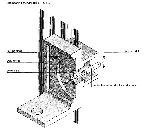
6.3.Additional alignment tolerances, cored hole formed by moving die element in same die half as datum
Additional total tolerance (TIR)to be added to tolerance in Standard 6.1
| Depth of Hole mm |
Tolerance mm |
| 0 to 20 | 0.10 |
| 21 to 25 | 0.11 |
| 26 to 30 | 0.12 |
| 31 to 40 | 0.14 |
| 41 to 50 | 0.16 |
| 51 to 63 | 0.18 |
| 64 to 80 | 0.20 |
| 81 to 100 | 0.23 |
| 101 to 125 | 0.27 |
6.4. Additional alignment tolerance, cored hole formed by moving die member in opposite die half to datum
Additional total tolerance (TIR) to be added to tolerance in Standard 6.2
| Depth of Hole mm |
Tolerance mm |
| 0 to 20 | 0.14 |
| 21 to 25 | 0.15 |
| 26 to 30 | 0.16 |
| 31 to 40 | 0.18 |
| 41 to 50 | 0.21 |
| 51 to 63 | 0.24 |
| 64 to 80 | 0.28 |
| 81 to 100 | 0.34 |
| 101 to 125 | 0.40 |
7. Miscellaneous standards
7.1. Machining stock allowance
In some cases machining will be needed to achieve the desired standard of accuracy and therefore an allowance of 0.25mm must be taken into account in addition to the appropriate tolerance to ensure the surface ‘clean up’.
7.2 Minimum section thickness
There is a relation between the size of a casting and how thin it can be there is no maximum wall thickness, but changes in wall section should accord with good practice for fillets, ribs and corners.
Minimum section thickness
| Size | Minimum Thickness | |
| Small | 10cm2 | 0.5mm |
| Medium | 300cm2 | 1.0 – 1.5mm |
| Large | Over 300cm2 | 1.5 – 2.0mm |
7.3. Taper for walls, ribs and bosses
Wall taper is normally between 1° and 2° per side. Shallow ribs, however, require more taper (5-10 °) although for ribs that are in line with shrinkage as, for instance, spokes of a wheel, small tapers are more acceptable.
7.4. Lettering
Minimum width of upstand 0.25mm, flank angle should be 25° or greater, and the height shall be equal to or less than the upstand width.
7.5. Threads
Thread form and size medium fit tolerances can be held on components up to 13cm projected area and 40g weight
| Metric BS3643 | |
| Minimum diameter | 8mm |
| Finest pitch | 1 mm |
| Tolerance preferred | 8g |
| Tolerance acceptable | 6e.6g.6h |
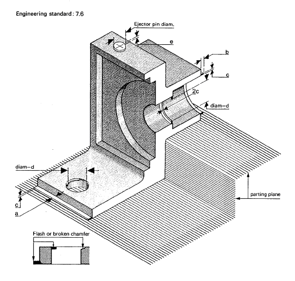
7.6. Standard of commercial trim
The figures below are a guide only, since much depends upon the number of parts cast per shot and the number of parts trimmed per single tool from each shot
| Approximate flash dimensions mm | |||||
| AreaPlan View cm2 | Width | Thicknessc | Cored hole d | Ejector pinse | |
| Parting Plane a | Moving Core b | ||||
| 0 – 20 | 0.2 | 0.4 | 0.8 | 0.1 | 0.2 |
| 21 – 70 | 0.3 | 0.7 | 1.4 | 0.2 | 0.4 |
| 71 – 200 | 0.5 | 0.9 | 1.7 | 0.3 | 0.6 |
| 201 – 600 | 0.8 | 1.0 | 1.9 | 0.4 | 0.8 |
| Over 600 | Please consult the diecaster | ||||
Finer limits can be achieved by using higher quality tooling and/or secondary operations but such limits are not termed commercial.
7.7 Taper of cored holes
Smaller tapers can be cast when necessary. Agreement of the die caster must be obtained.
Taper of cored holes
| Diameter mm |
Depth mm | Taper Deg min |
Tangent | Inclusive Taper mm |
|
| 3 | 10 | 3 | 0 | 0.0524 | 0.52 |
| 4 | 14 | 2 | 30 | 0.0437 | 0.61 |
| 5 | 18 | 2 | 12 | 0.0384 | 0.69 |
| 6.5 | 25 | 1 | 54 | 0.0332 | 0.83 |
| 8 | 32 | 1 | 36 | 0.0279 | 0.89 |
| 10 | 45 | 1 | 24 | 0.0244 | 1.10 |
| 12.5 | 60 | 1 | 12 | 0.0209 | 1.25 |
| 16 | 80 | 1 | 0 | 0.0175 | 1.40 |
| 20 | 110 | 0 | 51 | 0.0149 | 1.64 |
| 25 | 150 | 0 | 45 | 0.0131 | 1.96 |
Note 1: The depths and tapers shown are not applicable under conditions where smaller diameter cores are widely spaced and subject to full shrinkage stress.
Note 2: Holes to be tapped need less taper. In spite of slight production disadvantages arising from the smaller taper necessary, coring and tapping may still be more economical than drilling and tapping, whether or not a full thread is necessary. When the application does not demand a full thread, the hole should be cored to allow about 60 per cent of a full thread at the larger end and 75 per cent at the other end. If a full thread is essential, the taper should be removed by machining before tapping. Generally, the maximum threaded depth should not exceed twice the normal diameter of the screw and the depth of a blind hole should be in accordance with general engineering practice.
Design to Avoid Local Die Overheating
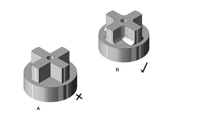
Small die features that are surrounded by the casting will tend to get hotter than the general die temperature. In extreme cases the result will be casting defects such as surface porosity, drag marks and cracks.
How to avoid hot spots by good component design
Good die design can often help to dissipate the heat developed in vulnerable areas but the best answer is to design out such features.
(A) and (B) provide the same functions but (B) eliminates right angled corners and so avoids local overheating.
Knife-edge projections on the die can cause local overheating and are also vulnerable to mechanical damage.
Designing to Avoid Moving Cores
Complex three-dimensional shapes are achieved by using moving cores, which slide in the die. However, if the component designer can achieve a satisfactory effect without these moving cores, the die will cost significantly less. For larger quantity production the extra cost involved with extra moving die members may be easily outweighed by the value of features they produce or by the reduction in material content of the casting that may be enabled.
How moving cores can be avoided
Leave the hole ‘open-ended’ eliminating the need for a moving core.
Method of producing a hole in the sidewall of a casting without using a moving core.
Note: this can only be achieved where the wall is angled to permit the die halves to separate, as illustrated in (A) and (B).
Avoiding Weak Die Features
Casting designs that demand the use of die features that are weak should be avoided. It is difficult to generalise about this subject but long slender die features that have stress raising notches are especially vulnerable to failure.
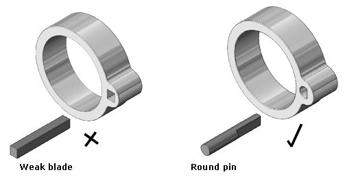
Blade-shaped core pins are weak and may easily break in service. Make holes as near circular as possible and machine details onto a standard round core pin. In the example the cored hole is required to provide a location on the right hand edge only. A semicircular hole is therefore acceptable and is a better design for tool making.
Cast Screw Threads
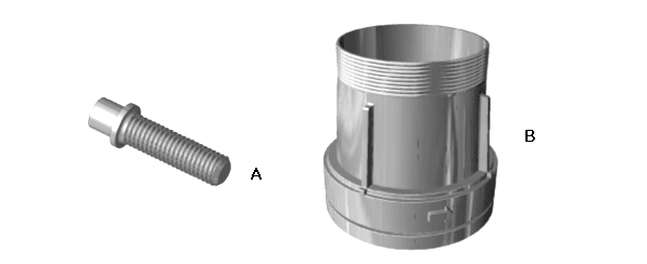
Most external threads can be cast provided that the parting line bisects them.
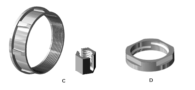
Except for a single turn thread, internal threads require an unscrewing core if they are to be cast. It is usually more cost effective to form the thread in a secondary operation.
External threads
(A) Full threads may be cast in but these require the die caster to maintain high standards of tool accuracy.
(B) Where the application permits, flats should be incorporated at the parting line so that trimming is simplified and pitch errors are accommodated.
Internal threads
It is usually cheaper to machine internal threads than to cast them in since the need to rotate the core to permit extraction slows down the casting rate (C).
Threads, which are either very coarse or steeply pitched, are an exception since they are more easily disengaged.
Internal threads consisting of a single turn can be produced without the need for rotating the core as shown in (D).
Design for Reliable Die Ejection
The ejector pin arrangement must ensure that the casting and runner are moved squarely and do not distort the component. In general terms an ejector pin must be provided close to every position where the casting will tend to grip the tool and positioned such that any strain that the ejector produces in the casting will tend to loosen it from the tool. This is largely the province of the diecaster and toolmaker to decide but casting design can make the job easy or difficult or impossible.
The ejector pins will leave small marks on the surface of castings unless special lugs are incorporated or the ejectors can act on the feed metal and overflow. The component should be designed such that these marks will not leave disfiguring blemishes on visible faces of the finished casting. Minimum ejector pin diameter is about 2.5mm but typically around 5mm.
Ejector pin marks may also be will be slightly raised or depressed. In non-critical situations allow for 0.4mm above or below the surface of the casting.
Ejector pin marks may also be surrounded by a flash of metal, especially after the die has produced a lot of castings. If end use permits ejector pin mark flash may not be removed but crushed or flattened.
Note : Complete removal of ejector pin marks and flash by machining or hand scraping operations should be specified only when requirements justify the expense involved in the extra operations.
Bosses
Bosses or similar metal concentrations that are heavier than adjacent thin walls will result in unequal shrinkage. This sometimes gives rise to so-called ‘shrink marks’ or ‘shadow marks’, which are actually shallow depressions on the face of the casting opposite the thickened section. Such marks may be unsightly, especially if the surface receives a lustrous finish. The effect can be minimised by making the variation in thickness as small and as gradual as conditions permit. Shadow marks can be masked by ribs or low-relief designs and seldom occur in sections over 2.5mm thick. Ribs are often faired to bosses where load concentrations occur in service and help to distribute the load over a larger area of the casting.
Tapped bosses are stronger than threaded studs because external threads cause a notch effect under shock loads. For this reason tapped bosses are always preferable and sometimes are as economical as threaded cast studs. However, the precaution must be taken to allow tap and chip clearance beyond the last thread of the hole, or else a through hole must be provided.
Cored Holes
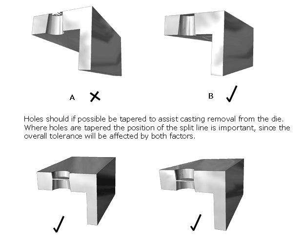
In many cases, drilling and machining can be completely eliminated by casting accurately cored holes. Zero taper is possible but should only be specified when absolutely necessary and the extra costs involved in casting production and die maintenance are justified.
For holes that are to be threaded, when the application does not demand a full thread, the hole should be cored to allow about 60% of a full thread at the larger end and 75% at the other end. If a full thread is essential, the taper should be removed before tapping or a much lower draft angle can be used depending on which route is the most cost effective. Generally, the maximum threaded depth should not exceed twice the normal diameter of the screw and the depth of a blind hole should be in accordance with general engineering practice. Holes to be tapped should usually be countersunk 2.5mm larger than the thread for ease of tapping and assembly, especially when the hole is cored.
Some techniques for designing cored holes
(A) A blind hole is preferable to a through hole, since there can be problems with flash.
(B) Where a through hole is required it may be preferable to cast a web at the parting line, which is subsequently removed.
Machining Allowance
Where machining is unavoidable an allowance of 0.25mm is appropriate. Avoid removing too much material, as this tends to expose any porosity present in the casting.
