Joining
Riveting
Riveting Techniques
Riveting displaces metal on studs or lugs by compression to form a head. The metal may be displaced by a single blow, or by a rapid series of relatively low intensity blows, or by spinning or wobble riveting. Riveting with a single blow (staking) offers the advantage that the shank is expanded in the hole making it more secure against vibration and several rivets can be formed over in a single operation. However larger deformations are easier to achieve with the other methods.
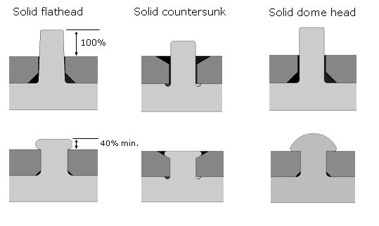
Rivet Types

![]()

![]()

![]()

![]()

![]()

![]()

![]()

![]()
Rivet Design
The casting must be designed to provide projections of the proper size and configuration. There must a surface to receive backup tooling, and all features of the casting affected by the imposed riveting loads must have sufficient strength.
Rivets need not be more than one diameter long and in no case should they be more than three diameters long.
Hollow (tubular) or half hollow rivets may also be used. The fully hollow rivet is preferred if this can be tolerated from the point of view of appearance, particularly when the rivet must be more than two diameters long.
There should always be a fillet at the base of the rivet. Preferably one quarter of the rivet diameter but 0.4mm as a minimum. The fillet can be below the surface of the casting if needed, to make assembly easier.
Two relevant parameters are the ratio (R) of the length to diameter of the metal to be cold worked, and the ratio (K) of the length after and before cold forming. R should not be less than 0.5 and K not less than 0.4
The undercut at the base of the stud is somewhat weaker than a fillet, but it satisfies the need for a tooling radius without requiring a radius or chamfer on the mating part.
The Compressive stress at 20°C in Alloy ZP3 as a function of R and K is shown below. When two members are rigidly attached, high compressive stresses in the range of 800 MPa, which are well above the 410 MPa compressive strength of Alloy ZP3, may be desirable. At these levels, the portion of the stud confined within the mating member will expand radially, forming a mechanical lock that enhances rigid attachment. The data applies only to ZP3, but will serve as a qualitative guide for other zinc alloys. Similar data generated at temperatures to 80°C indicate that ductility increases, but the stresses induced and consequently the deformation forces required are not reduced significantly.
Where joints are designed to permit rotation, such as a knob attachment, stresses in the areas of the stud, which lie within the mating member, should be kept below 410 MPa to prevent expansion and retain the design clearances. Stress levels can be controlled by selecting higher values of R and K to limit the stresses in the cold worked area, and by reducing the ratio of D/Do to further reduce the stresses in the larger section of the projection.
Relevant dimensions for a riveted fastening that permits rotation between the members, such as a knob attachment.